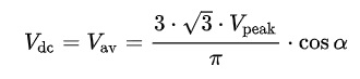
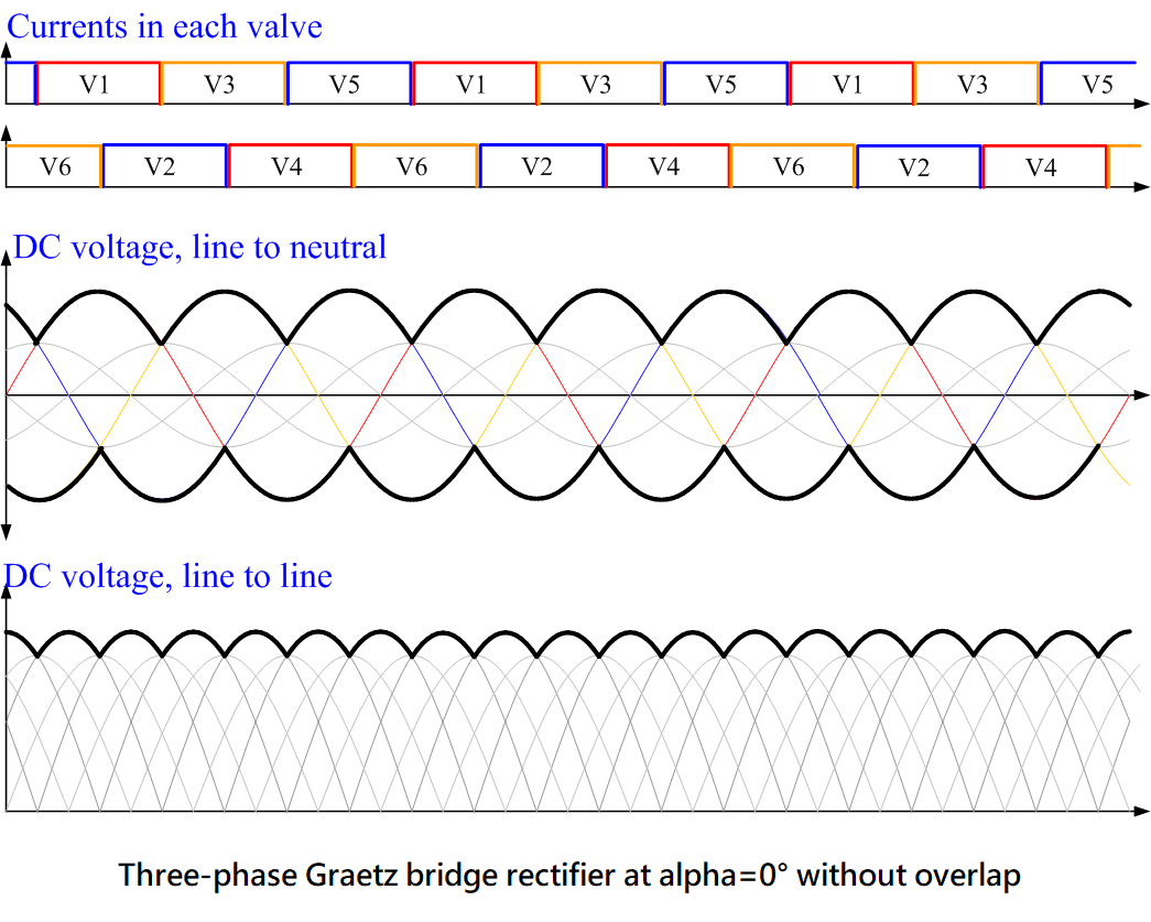
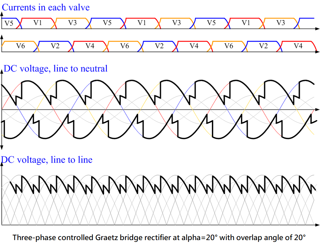
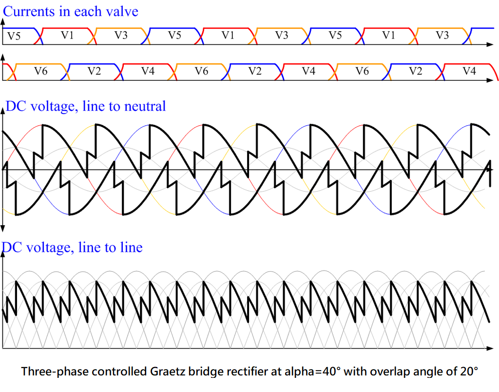
The controlled three-phase bridge rectifier uses thyristors in place of diodes. The output voltage is reduced by the factor cos(α):
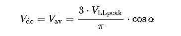
Or, expressed in terms of the line to line input voltage:
VLLpeak: the peak value of the line to line input voltages,
Vpeak: the peak value of the phase (line to neutral) input voltages,
α: firing angle of the thyristor (0 if diodes are used to perform rectification)
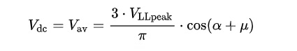
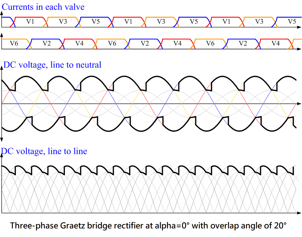
The above equations are only valid when no current is drawn from the AC supply or in the theoretical case when the AC supply connections have no inductance. In practice, the supply inductance causes a reduction of DC output voltage with increasing load, typically in the range 10–20% at full load. The effect of supply inductance is to slow down the transfer process (called commutation) from one phase to the next. As result of this is that at each transition between a pair of devices, there is a period of overlap during which three (rather than two) devices in the bridge are conducting simultaneously. The overlap angle is usually referred to by the symbol μ (or u), and may be 20 30° at full load. With supply inductance taken into account, the output voltage of the rectifier is reduced to:
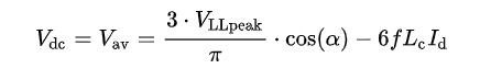
The overlap angle μ is directly related to the DC current, and the above equation may be re-expressed as: